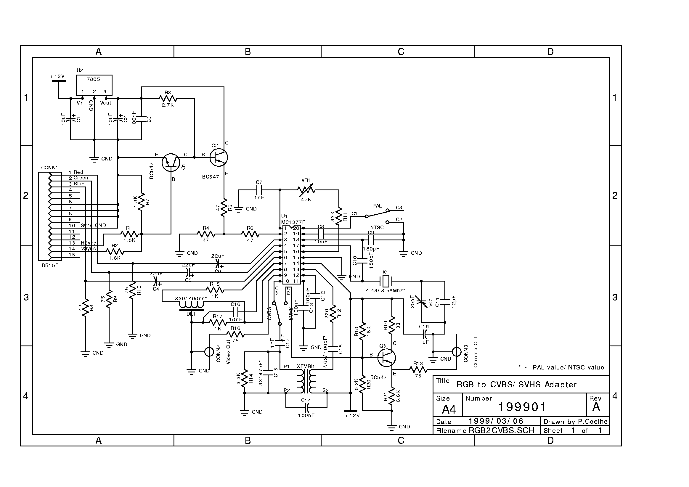
Part List:
- Components needed:
1 Metal box
1 DC socket, male
1 PCB
2 switches/jumpers
CONN1 = Mini DB15P socket, female
CONN2,
CONN3 = RCA socket. female
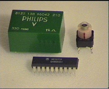
DL1 = 300ns Philips delay line. Motorola asks for a 400ns, and "Radio Plans" magazine uses a 470ns delay line in their schematic. I guess you should use whatever you get...
Q1,
Q2,
Q3 = BC547
U1 = Motorola MC1377P
U2 = 7805, voltage regulator
VC1 = 25pF, variable capacitor. Doesn't need to be exactly this value.
VR1 = 47K, variable resistor
X1 = 4.43Mhz crystal (PAL), 3.58Mhz (NTSC)
XFMRI1 = Chroma bandpass transformer
R1,
R2,
R7 = 1.8K ohm
R3 = 2.7K ohm
R4,
R5,
R6 = 47 ohm
R8,
R9,
R10,
R13,
R16 = 75 ohm
R11 = 33K ohm
R12 = 220 ohm
R14 = 3.3K ohm
R15,
R17 = 1K ohm
R18 = 16K ohm
R19 = 33 ohm
R20 = 8.2K ohm
R21 = 6.8K ohm
C1,
C2 = 10uF, 16V
C3,
C12,
C13,
C14 = 100nF
C4,
C5,
C6 = 22uF
C7,
C17 = 1nF
C8 = 10nF
C9,
C10 = 180pF
C11 = 12pF
C15 = 33pF (PAL), 47pF (NTSC)
C16 = 10nF
C18 = 62pF (PAL), 100pF (NTSC)
C19 = 1uF
You can also get the file version, if you want to.
Below is a picture of my delay line and the chroma bandpass transformer, having the MC1377 below for size comparison.